(click photo to enlarge) |
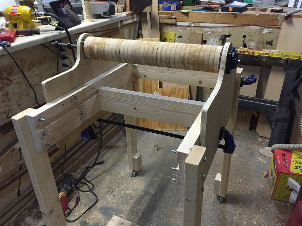
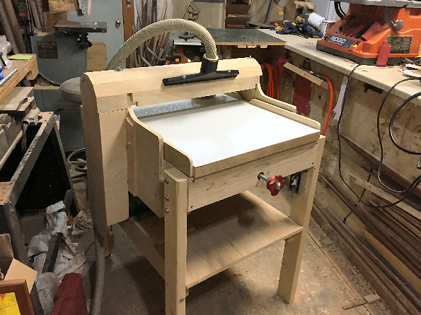
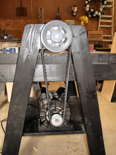
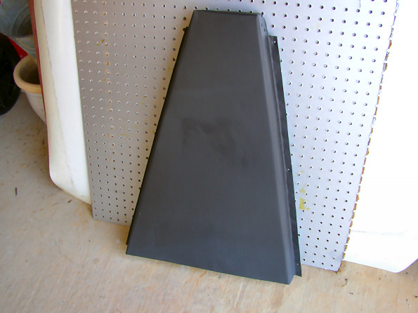
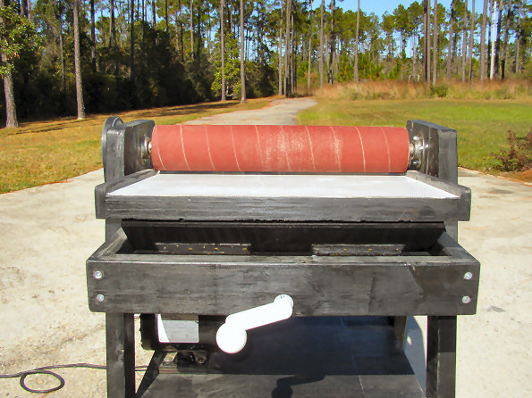
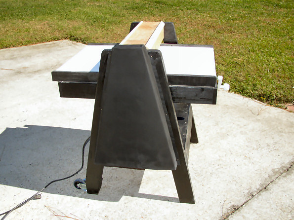
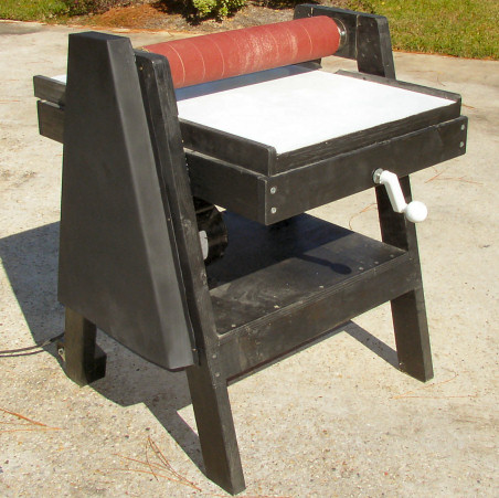
This is my shop built 22 inch tilting table drum sander.
In preparing to build my version of the drum sander (sometimes called a thickness sander), I looked at commercial versions and several shop-built versions on the Internet. Most shop built models used variations of the basic plans published in "Power Tools and Accessories", a good, solid machine, but I had several requirements that I wanted to incorporate that made this option unacceptable, so I went at it on my own.
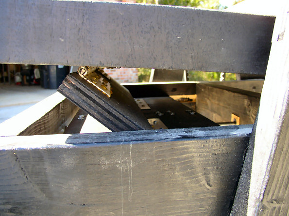
First, I found that most of the shop-built sanders used a single screw mechanism to raise and lower the table, i.e. a threaded rod or bolt located at the front of the table that, when turned, raised the table at a single point. This (to me) seemed to be a bit unstable unless you used some sort of locking mechanism on the sides to hold them tight. Without side locks, no matter how well the table is secured at the far end, you still had the potential for wobble or misalignment on the sides. I wanted a single solution to lift the table securely across its entire width, without the need for any sort of stabilization. I came up with a hinged sled mechanism that fills the bill nicely, and is ultra stable.
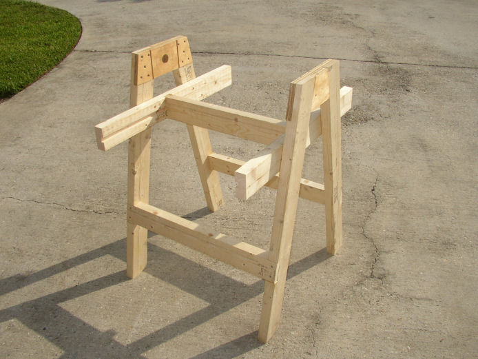
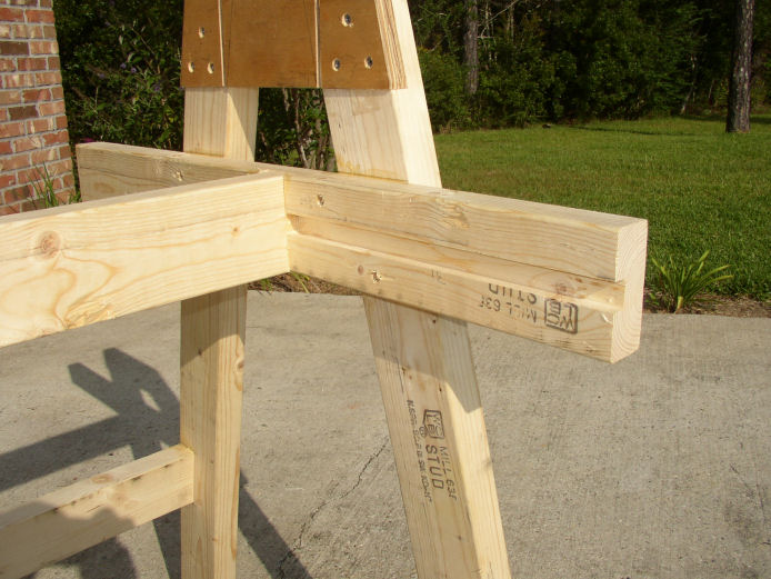
I also did not like the vertical stand...all of my shop tools have canted legs, titled at around 15 to 17 degrees, which makes them very stable and less prone to tipping. So, I wanted a stand that had these canted legs.
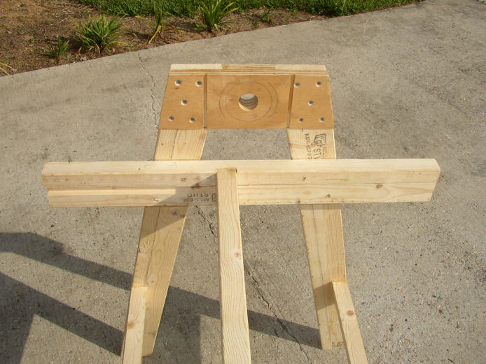
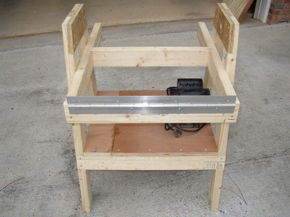
I did not particularly like the pillow block bearing sitting up on top of the stand of many of the shop built units I saw. Again, (yes, I am a stability freak!) it just looked like it would/could weaken over time and allow wobble or misalignment to creep in. So, I used three bolt flange bearings I found at an Internet surplus center (all of my sources are included below). These bearings bolt right to the sides so there is lots of stability.
Finally, I have never liked the "hanging motor" type of tensioner. I like everything nice and tight. So I bolted my motor flat to the stand and used a v-belt that was the correct size for the pulleys. Tightening the motor to the table pulled the belt exactly tight enough without putting much stress on the bearings.
Other features I found on shop-built sanders were difficult to improve on so I incorporated them as I went along.
Here is my construction as it progressed. As of this time, I have yet to complete the sawdust collection; my sawdust collection system consists of a 6hp shop vac, so I don't have a ton of suction...I need to be conscious of how I direct the suction to maximize its effectiveness. I am still thinking of what to do there.
Here is how it went! Let me know if you want me to expand on anything! Note: click on any picture to enlarge it in a new window.
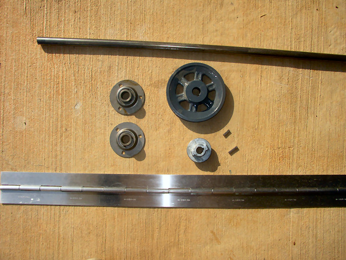 |
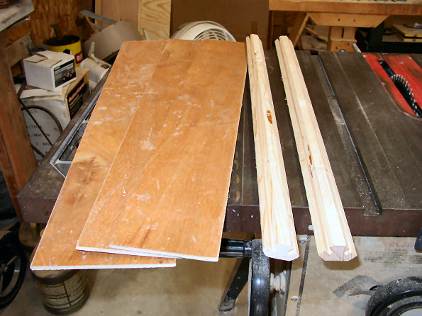
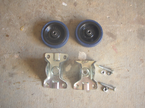
Here are the major hardware parts. You can see the 3/4" keyed shaft I used for the drum. There are the two flange bearings. Two pulleys, and key way keys. Best of all was this massive piano hinge. Turns out is was military surplus and really thick aluminum. No holes either, so I got to drill my own only where I needed them. Here is the parts list with stock numbers and source:
| Part Number |
Description |
Price |
| 1-2982-75-3 |
3/4" X 36" KEYED SHAFT |
$22.75 |
| 1-1974 |
2.25" DIA 5/8" BORE PULLEY |
$1.99 |
| 1-BK57-C |
5.45 O. D. 3/4" BORE PULLEY |
$9.00 |
| 1-2870 |
3/4" 3 BOLT FLANGE BEARING (2) |
$7.90 |
| 1-2994 |
2 X 1 SWIVEL PLATE CASTERS (2) |
$3.78 |
| 1-2283 |
3" x 50" ALUMINUM PIANO HINGE |
$4.99 |
Source: http://www.surpluscenter.com |
Note: click on any picture to enlarge it in a new window.
Note: click on any picture to enlarge it in a new window.
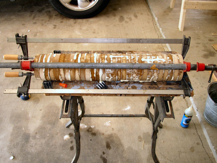 |
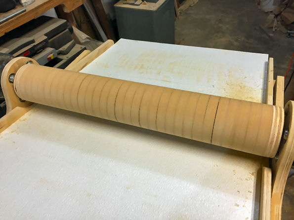
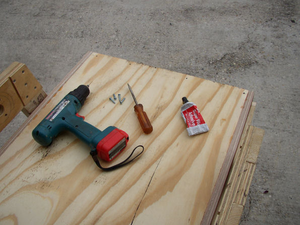
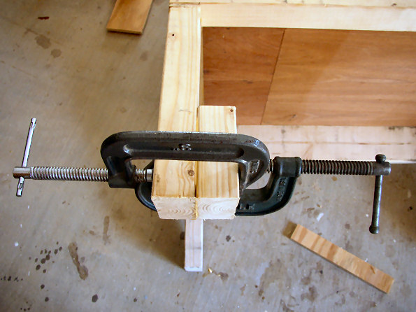
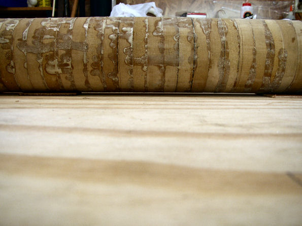
Drum construction is pretty much like all of the other shop-built sanders. I used MDF, cut 4 inches in diameter. The MDF was from some cabinet doors I had laying around from a neighbor who replaced his kitchen cabinets. I rough-cut the 32 disks with a jig saw then I used a circle-cutting jig on my router table with a straight cutting bit to shape the disks. Here they are glued together using Gorilla Glue. You can't see the shaft behind the pipe clamp.
|
 |
 |
 |
 |
|
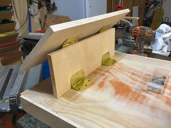
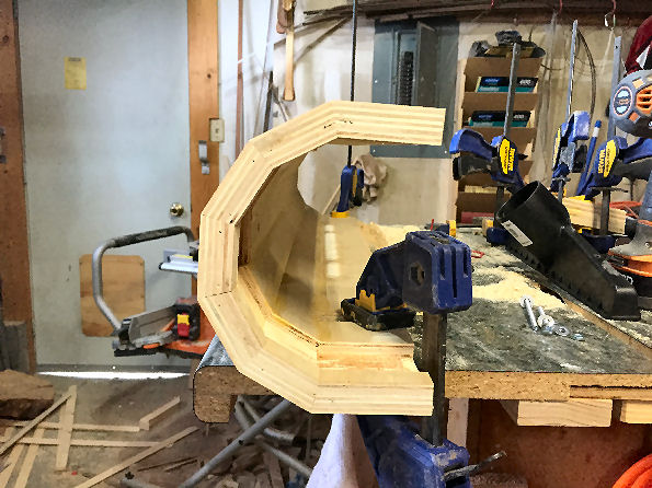
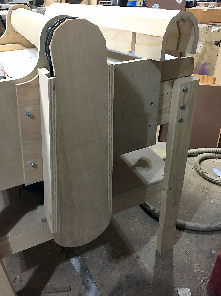
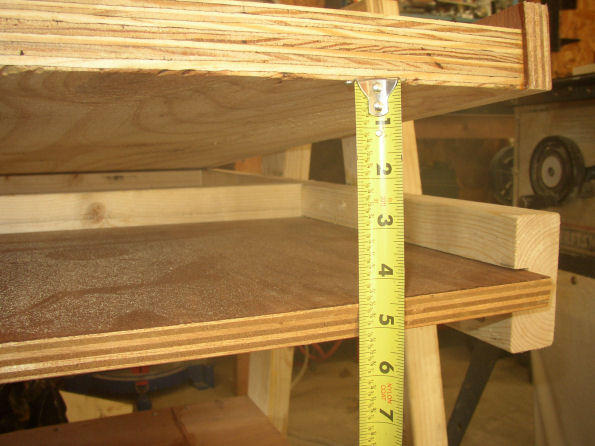
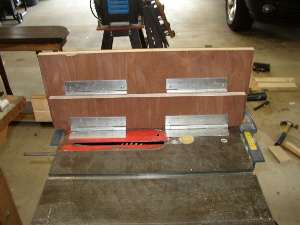
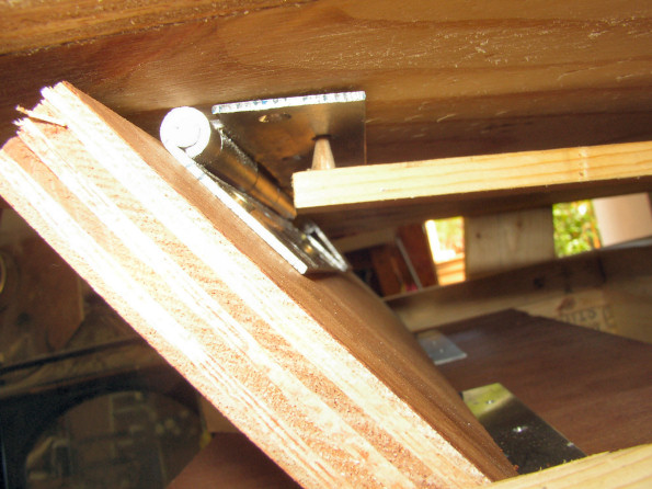
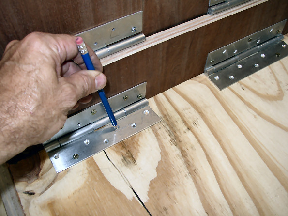
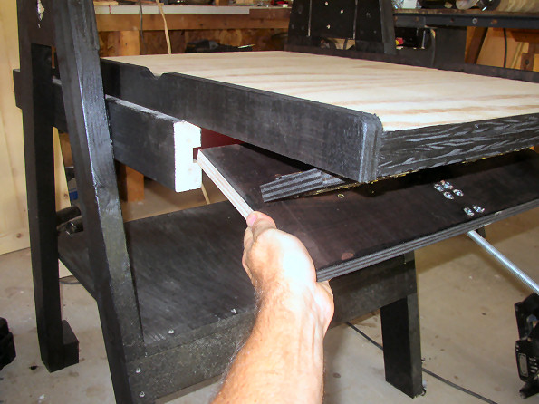
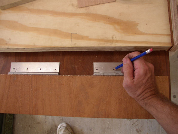
Sled construction. First, I cut a piece of that cabinet grade plywood to fit in the sled tracks in the frame. It is not cut to size yet, since the size will be determined by how far the sled needs to travel back and forward. Next, I raised the table to within 1/8 inch of hitting the drum (first picture), then with the table held at that position, I measured the distance from the top of the sled to the bottom of the table. This will dictate the height of the riser, or the piece of wood that does the lifting. With this dimension, I cut the riser (seen in the third photo). I mounted the hinges (left over from that massive piano hinge) onto the riser, then mounted them onto the sled. To determine where the hinges would be positioned on the sled, I placed the riser on the sled and moved it around until the riser was short of being 90 degrees. In other words, when the table has been lifted all the way up, the riser will not quite be straight up, it will be maybe 60 degrees to the table.
|
|
 |
 |
 |
 |
|
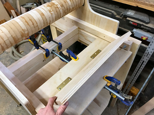
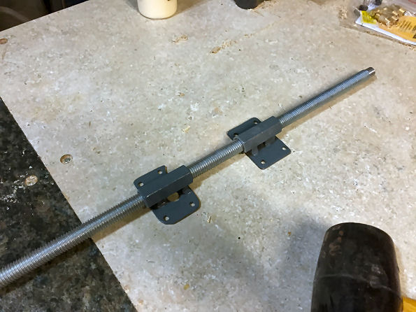
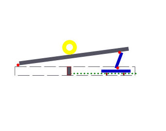
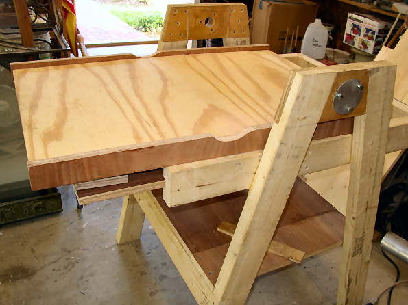
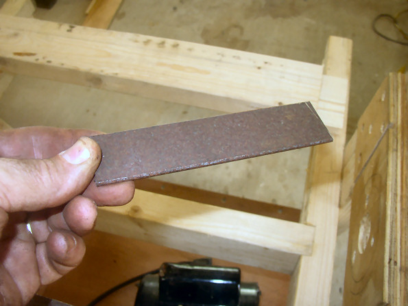
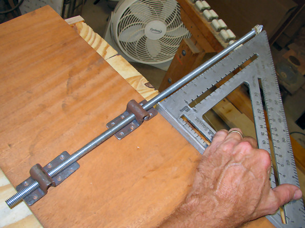
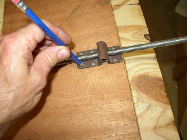
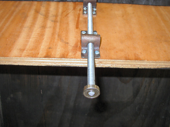
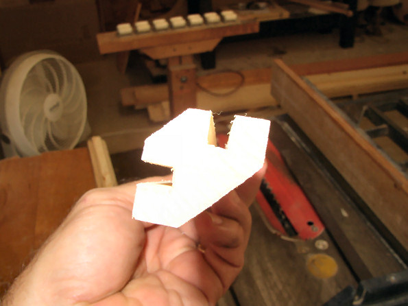
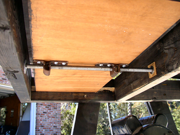
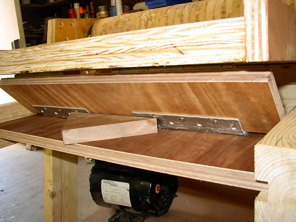
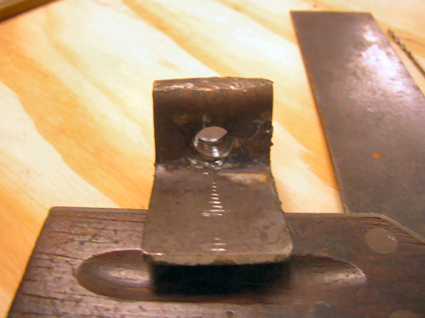
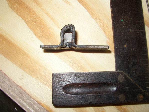
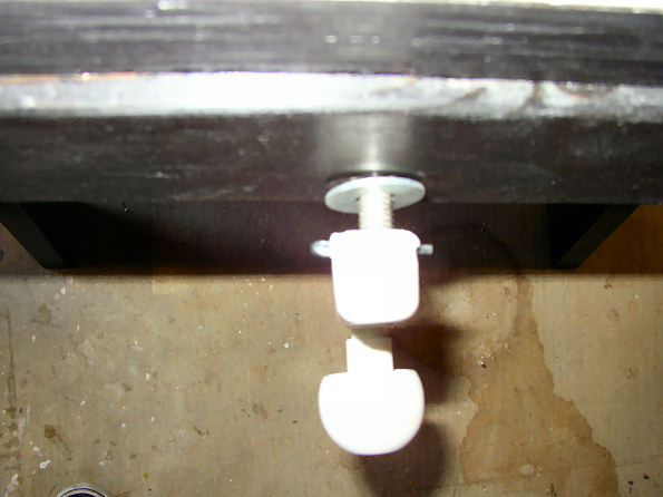
Table elevation will occur as the sled travels forward and backward in the tracks. To control where the table stops in the all-up and all-down positions, the sled ends are cut so that they bump into the table supports in the front and back of the sled. In other words, when the sled goes back as far as it can go, the table should be just reaching its full-down position. And, when the sled travels forward as far as it can go, the table should be within 1/8 inch of the sanding drum. In photo 1, I have blocked up the sled hinge so I could take the picture. You see that the front of the sled has been trimmed so that it now will butt up flat against the front table support (which will be rabbeted 3/4 inch in). Now, I needed to build the height adjustment mechanism. The sled will travel back and forward by means of a threaded rod running through the front table support to the middle table support (the space occupied by the sled). The sled will have two nuts fastened to it so that when you turn the threaded rod, the nuts will move along the rod taking the sled with them. I thought about this arrangement for a long time, specifically, how can I attach the nuts securely to the sled. Remember, these nuts will bear the force of the downward pressure as you are working on the table, so they need to be really securely mounted! I decided to use steel flat stock I had left over from another project. The flat stock was something like 1 1/2 inch by 1/8 inch stock, standard stuff you can get at any hardware or home improvement store. I cut off a piece about 5 inches long (photo 2). Using the vice and a big hammer, I created the little "nut holder" bracket in photo 3 and 4. As you can see in photo 4, the nut is already installed in this photo. Since I didn't have any welding skills, I went to a friend of mine who has one of those wire welders and he spot welded the bottom of the nut onto the bracket. To do this, I slipped the nuts into the brackets I made and then I ran the brackets and nuts onto the threaded rod. This guaranteed that when they were welded, the would be properly aligned. |
|
 |
 |
 |
 |
 |
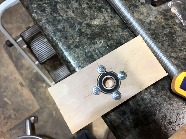
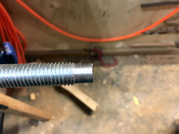
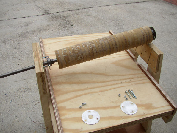
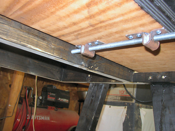
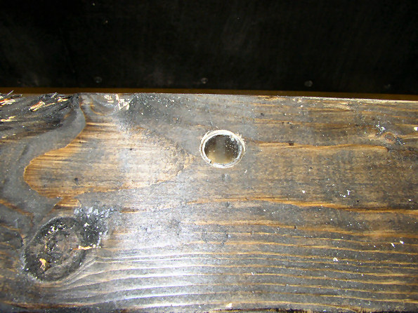
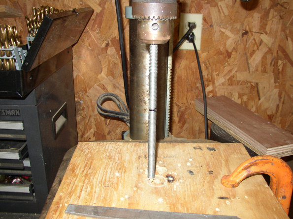
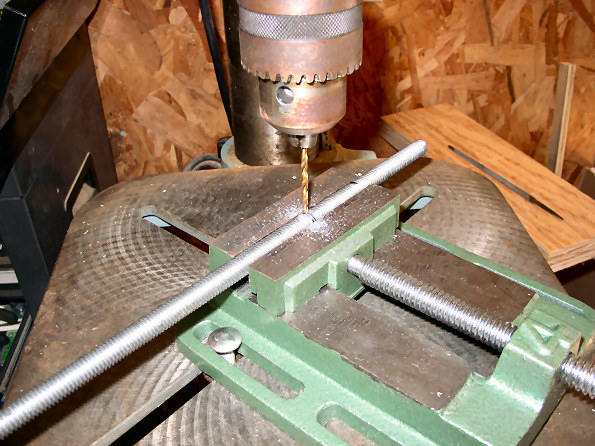
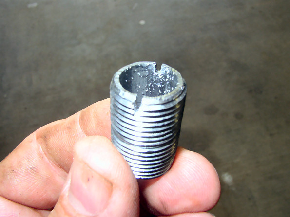
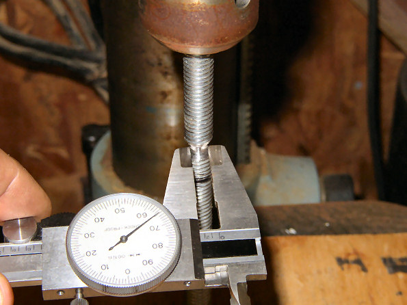
To prevent the threaded rod from wallowing out the hole in the front table support, I made a bushing from a 1/4 inch iron pipe nipple, available at any hardware store. The threaded rod fits very nicely into this pipe nipple with very little slop. First, I cut a little slot in it for my screw driver to fit into, then I screwed the pipe nipple into the front support. The middle support needs something different...as you turn the threaded rod to elevate the table, the pressure of the table will be pushing the threaded rod back against the middle table support, so I need some sort of thrust washer arrangement. Here's what I decided to do... I had some old roller skate ball bearings laying around. These are available pretty cheaply at at most sporting goods stores. However, the inside diameter of the bearing is a little less than 1/4 inch (must be metric), too small for the 7/16 threaded rod. So to bring down the size of the rod, I installed the threaded rod in my drill press and clamped on a board with a 7/16 inch hole to keep the rod from wobbling. Then I spun the rod at a fairly slow speed and used a metal file, held against the rod, to whittle away at it. Once the size was right, I removed the rod from the drill press and cut off the excess, leaving the small piece on the end of the rod. In photo 5, see how the rod now fits perfectly into the bearing.
|
|
 |
 |
 |
 |
|
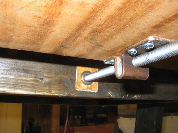
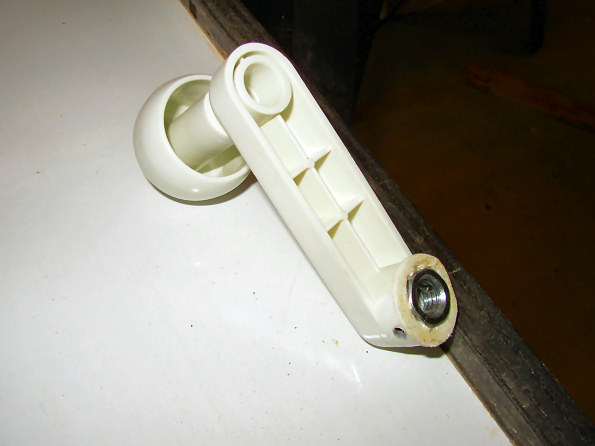
Now I needed to make the bearing holder in the middle support. I decided that the pine would be too soft to offer good bearing support, so I cut a piece of Maple into a block about 1 1/2 inches by 1 1/2 inches by 1/2 inch thick and drilled a hole just deep enough for the bearing to fit flush. Then with a wood chisel, I cut out a square hole in the middle table support for the bearing block and glued it in. Photo 1 above shows the bearing block installed and the threaded rod fitting nice and snug. This should give a really secure surface for the rod to push against, as well as making turning the rod very smooth! Even though the critical thrust is always to the rear, I didn't want the threaded rod sliding forward either, so I drilled a small hole at the point where the rod just met the front table support. Here, I will install a big flat washer and a cotter pin to keep the threaded rod from sliding forward. I drilled another hole up toward the front of the threaded rod to hold the hand crank. I picked up the crank at our local overstock store. They carry a bunch of stuff all the time from stores that have closed, had fires, etc. The crank looks like it came from some sort of small ice cream maker. The crank had a tiny hole on it for a shaft or something, but I took a 7/16 inch nut and put it on my electric stove burner for a few minutes until it was hot enough to melt through the plastic, then I pressed the nut into the crank, letting the nut melt itself into the plastic. Next I drilled a hole in the side of the hand crank, through the nut, that aligns with the hole in the threaded rod, then I screwed the crank onto the rod and inserted a cotter pin to keep if from spinning off. |
|
 |
 |
 |
 |
|
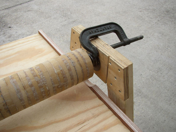
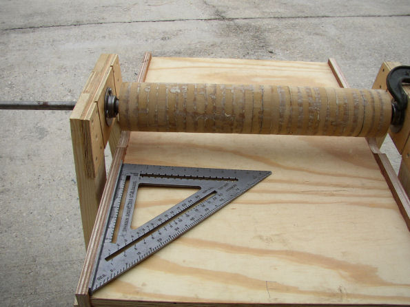
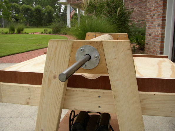
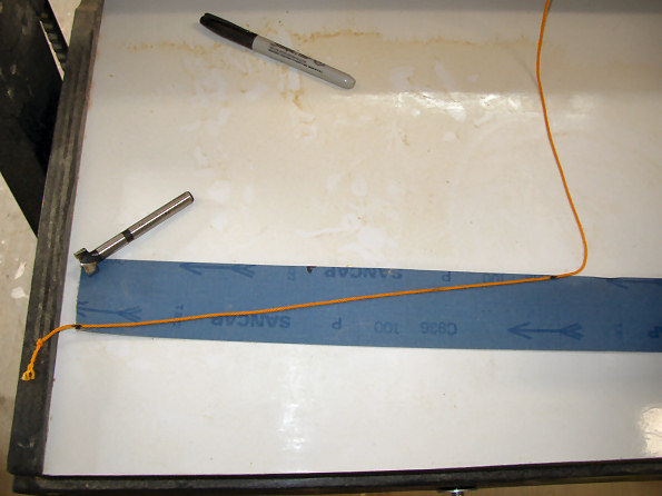
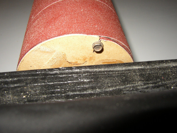
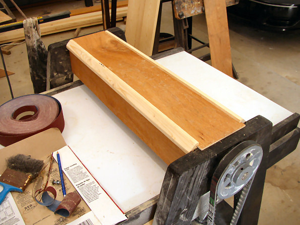
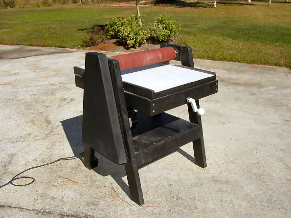
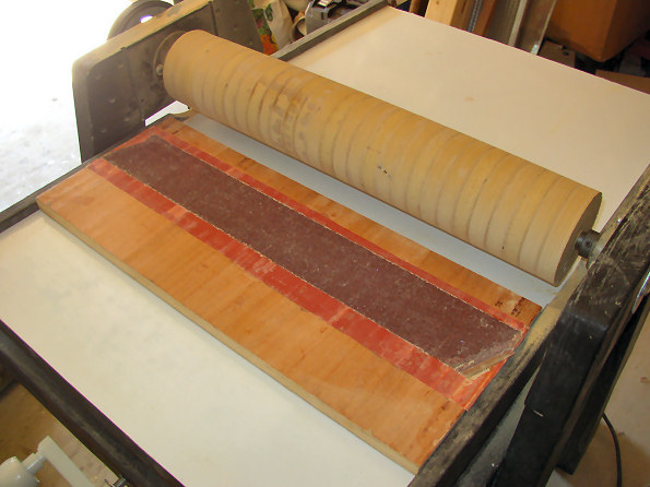
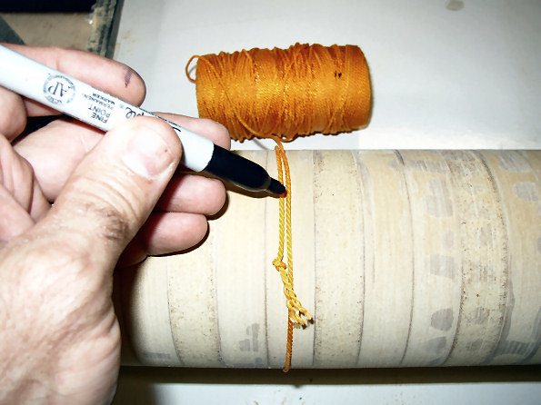
I don't have any pictures of attaching the surface to my table, but that is pretty standard stuff. I found some 4' by 8' fiberglass sheets at my local salvage construction supply yard. It looks like it was for shower stalls or something. It is really thin, like maybe 1/32 inch thick. Since it was only $5.00 per sheet, I brought it home! I cut out a chunk the size of my table and laminated it to the table with contact cement. It makes a really nice, shiny, surface, and appears to be really tough and the wood slides easily over it. You will see it in some of the following pictures. Anyway, next it was time to true the drum, which again, I did just like the other shop-build drum sander builders did. I hooked up the motor to the pulleys (Photo 1), then I used an old belt sander belt glued to a flat piece of plywood. I just slid the plywood in and out under the drum as it spun until it was perfectly round and true to the table. Next (again copying the other builders) I wrapped a string around the drum and marked the string for the diameter of the drum. Then, I used this string to cut the sand paper belt I bought on eBay. As you can see, the string gives you the exact dimension to cut your belt so when it is wrapped around the drum, it doesn't hang over.
|
|
 |
 |
 |
 |
|
***UPDATE***
Okay, I finished adding the suction device to the dust hood...it works really great!
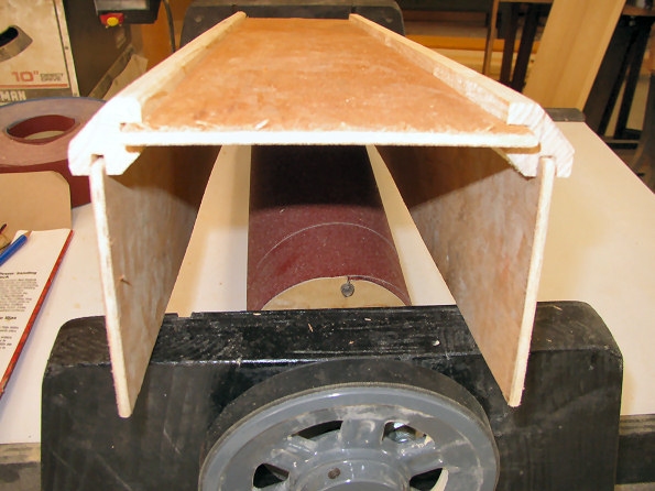
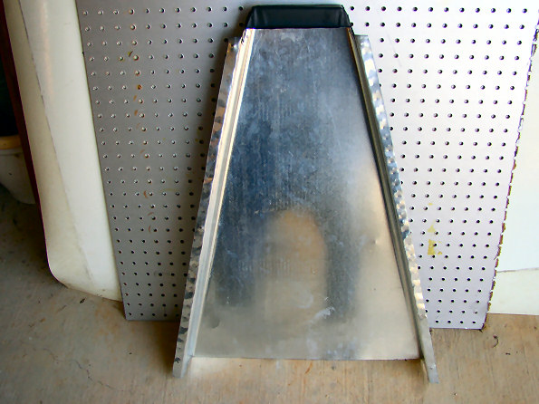
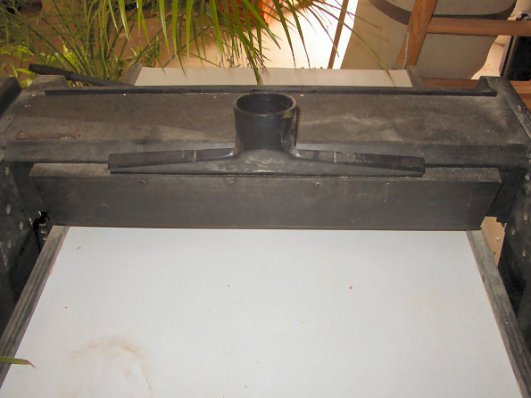
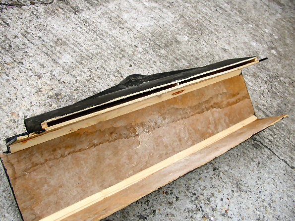
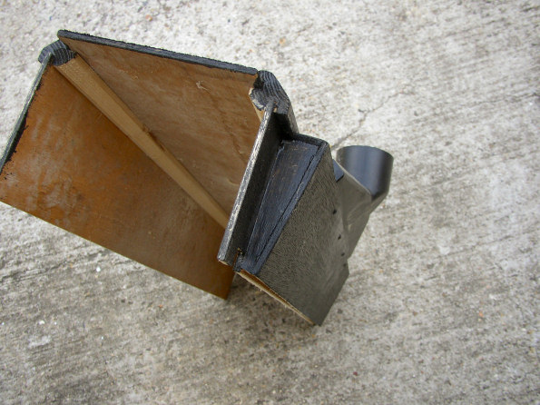
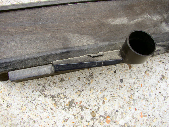
I took that really wide floor cleaning attachment that comes with the shopvac and I modified it to fit on my dust hood. When you realize that most of the dust comes right off of the front of the sander as you push the wood through, I figured rather than just stick a connection on top the dust hood like some folks do, I wanted to catch the dust as it is generated! This is what I have done...I made a narrow chute that has about a 3/8" opening (more or less) and runs the width of the drum. This chute gets wider toward the top so that it can fit around the vac attachment. I placed a small spacer rib in the center of the chute to keep the thin luan plywood from bending in or out at this point...you can kind of see the end of that rib in the center of the chute in photo 2 above. I am thinking about adding one of those little sweeper-seals to the front of the chute to REALLY concentrate the vacuum toward the work piece. I just haven't found such a thing yet.
When the sander is operating, I have the shop vac hooked to the attachment, the hose running straight up and over to the vac, totally out of the way. As you would expect, the suction is amazing since all of it is totally concentrated to that single little slit in front of the sanding drum. I am really happy with the way it turned out. |
|
*** Update January 2015
Here is net-maker Alan Crist's version of the drum sander. He made some improvements to the design so you might want to consider some of his alterations if you are thinking of building one. Check out his web page to see what he makes!
Alan says - Well I got it all finished and am super happy. I tried it tonight and it works great! One of the main reasons I built this is to help me more easily sand down fishing nets that I make. It is a fun hobby that I started a few years back and the most problematic part was the initial sand down after the glue up as there is dust/glue dust everywhere and it is hard to sand both sides down to an even thickness across the entire net. I ran a couple nets that I recently glued up through the sander tonight and it worked awesome. Anyway, thanks again, Jim, for the inspiration and all the instructions. Could not have done this on my own.
Many, many thanks to the other drum sander builders who have taken the time to post their projects to the Web. You guys got me motivated!
Home-made Thickness Sander
Shop Made Drum/Thickness Sander
Homemade Drum Sander
A Shop-Built Drum Sander by Ray Lanham
Sturdee’s drum sander
Also to the guys on the shop-built tools forum for their inspiration.